Devlog Week 1 - Basic Rendering
Monday, June 20, 2022Welcome to my devlog! Here I’ll be recording development of the projects I’m working on. I’m starting off with a basic Minecraft clone using OpenGL and C++, and this week I worked on setting up a lot of the rendering framework for the game. I also got a basic chunk of 16x16x16 blocks rendering.
Basic 2D rendering
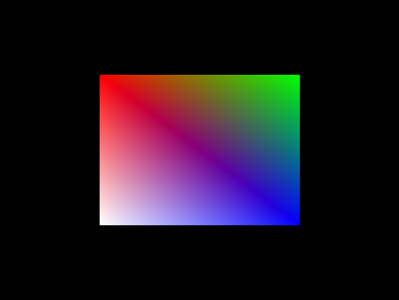
To start things off, I set up an object-oriented rendering API and got it to render a basic colorful rectangle. This API is super basic but it works pretty well for my purposes, and I designed it to be easily extensible. So I should be able to expand it when necessary and use it for the full game.
Here’s an overview of all the classes in it: - Shader – Pretty basic class that handles compiling code for individual shaders. - ShaderProgram – Handles shader program code. Also has a method called Use() which binds the shader. - VertexBufferObject – Handles OpenGL VBOs. Intended to store models of individual objects to render. - VertexArrayObject – Handles OpenGL VAOs. Renders a list of queued VBOs with a predefined shader.
So to draw this rectangle, I: - Made a ShaderProgram comprising of Shaders necessary to actually render the object - Made a VertexBufferObject and added the vertices of the rectangle to it - Made a VertexArrayObject with the ShaderProgram defined as the VAO’s shader - Every frame, registered the VBO to the VAO to draw
Uniform troubles
So as it turns out, in making my rendering API, I completely forgot about uniforms! For those who aren’t familiar with OpenGL, uniforms are external data sent to the GPU to render that aren’t tied to a vertex. Color usually isn’t a uniform since each vertex can have a different color. But if we want to have, say, a moving camera, uniforms are usually a pretty good way to pull that off.
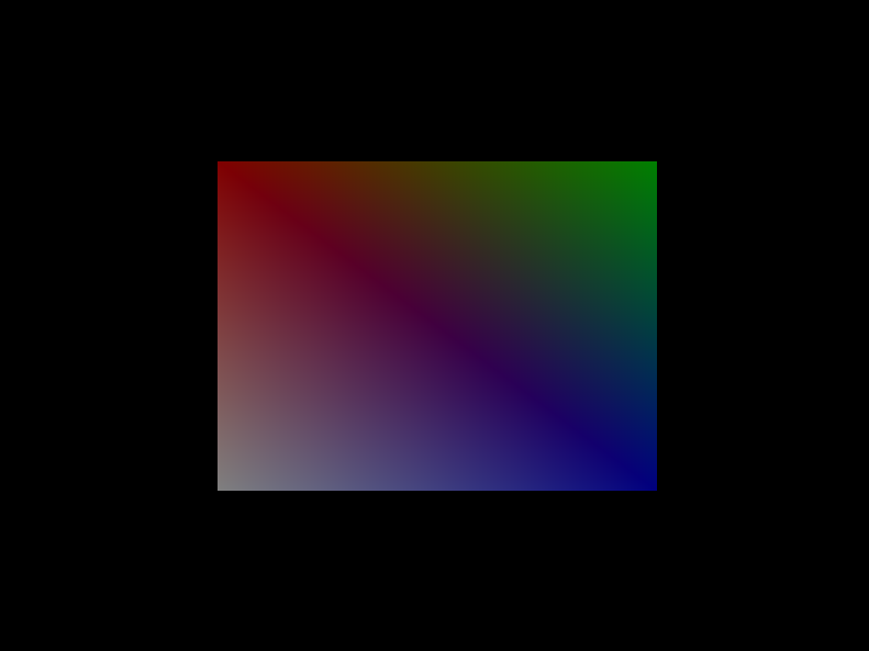
I realized that a pretty good way to set up uniforms would be using inheritance. For my 3D renderer, I made a new class that extends VertexArrayObject called VAO3D. I made some abstract methods in the parent class to handle uniforms, and overrode them in VAO3D to add a new one to dim the color of the rectangle.
Of course, this kind of color manipulation isn’t necessarily what we need to move forward with 3D rendering. It was intended as a test for my new uniform system. But now that I’ve got it working we can move on to more advanced techniques.
Matrix multiplication
If the title of this section scares you, it might be worth reconsidering going into computer graphics.
Interestingly enough, in graphics, we usually store coordinates in 4D. There’s your typical x, y, and z coordinates, but there’s actually a fourth one called w. Changing w modifies the scale of the scene, as the 3D coordinate (x, y, z) is mapped to the 4D coordinate (x*w, y*w, z*w, w). This coordinate system is called “homogeneous coordinates.”
We use homogeneous coordinates because of transformations. With a 4D coordinate system, we can use matrix multiplication to represent all three basic transformations (translation, rotation, and scaling). So they’re really useful for creating a complex 3D scene.
For this project, I’m using a library called GLM (short for OpenGL Mathematics). GLM is able to easily handle all these transformation matrices we need to use. So it’s a really convenient library to use when working with graphics in C++.
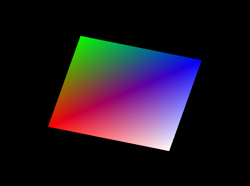
Using a rotation matrix generated with GLM, I was able to make the rectangle spin around. The matrix was a uniform, and the matrix multiplication was performed in the shader, as GPUs have built in matrix math support. GPUs are also specialized in performing this kind of math quickly so it’s usually a good idea to have them handle it.
Going 3D
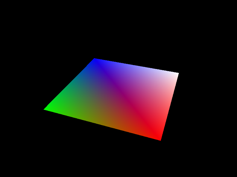
Once we’ve got transformation matrices, making a scene 3D isn’t actually that hard. When rendering 3D scenes, there are 3 matrices we need to worry about:
- The model matrix handles all our transformations. Translations, rotations, scales, they all go in here.
- The view matrix handles positioning our camera. GLM can easily make a 3D view matrix with the glm::lookAt function.
- The projection matrix handles projecting our 4D homogeneous coordinates to 2D screen coordinates. Again, GLM makes this easy with the glm::perspective method. It also supports isometric coordinates if you prefer those.
Once we’ve got all of the matrices defined as uniforms, it’s just a matter of multiplying them in the correct order (final coordinates = P*V*M*original coordinates) and then we’ve got 3D rendering!
Interestingly enough, the projection matrix also takes the window’s aspect ratio as an argument, so we actually get a more accurate depiction of our scene than we had before. What once appeared to be a rectangle was actually a square – it only looked like a rectangle since it was stretched out by the window. If we changed the window size we could get a square or a vertical rectangle instead.
The first cube
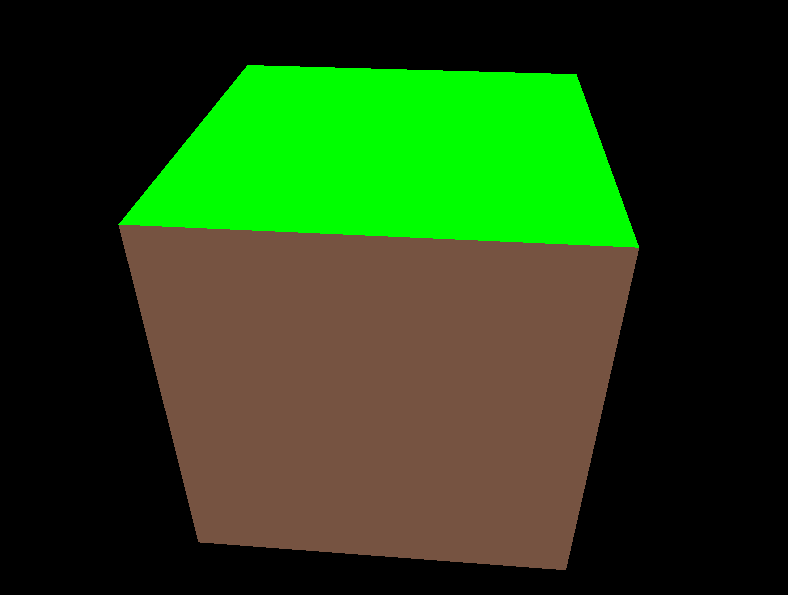
Can’t make a Minecraft clone without cubes! I changed the model we’re rendering to a cube (basically just added 5 more rectangles and changed the colors). Looks pretty nice.
Something worth mentioning for anyone following along: you’ll get some wonky rendering if you just start working with 3D models from the basic 3D matrices alone. By default, OpenGL doesn’t know that it should render stuff that’s further away first – so without fixing that, you’ll get the back of a wall rendering in front of the front sometimes.
We can fix that by using a “depth buffer” (or “z buffer”). The only changes necessary to our code are that we need to clear the depth buffer alongside the color buffer every frame, and we need to enable OpenGL’s built-in depth test. Once we’ve got both of those, it should work like a charm.
First-person navigation

At this point in development, I had the cube spinning around in front of a static camera. However, I wanted to be able to actually fly around, so I implemented a first-person camera. Here’s how it works.
The camera’s data is currently stored in the VAO. This will likely change at some point to a dedicated Camera class, but I haven’t done that yet. The data stored consists of a 3D vector representing the camera position, and 2 floats representing the camera pitch and yaw (no roll for now).
To actually update the view matrix with this data, I’m using a clever trick with glm::lookAt. Of course, for the “camera position” argument I pass the camera’s position. But for the point it’s looking at, I use the pitch and yaw to find a point on the unit sphere, and add that point’s position to the camera’s position.
The computation of this “forward vector” is also useful for actual movement. I’m able to use it, as well as a similarly computed “right vector,” to move the camera in the direction it’s looking. Pretty straightforward, and now I’ve got first-person controls with WASD to move + arrow keys to rotate. (I’ll change that to mouse rotation at a later date.)
Textures
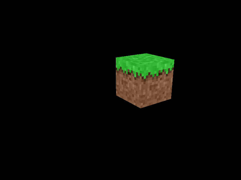
You might’ve noticed that my block was a little barren before. That’s because it was just solid color, rather than actually having a texture! So I fixed that.
On the shader end of things, textures are pretty straightforward. You have to pass 2D texture coordinates with each vertex, and a sampler2D to represent the texture. Once you have that you can use GLSL’s texture method to obtain the texture color for each fragment. So you just multiply that by your vertex color and you’re home free.
The tricky part is getting the sampler2D set up. OpenGL has a very specific way to set up textures, so I made a new Texture class to handle it. I also modified VertexBufferObject to store a reference to a Texture – said texture is bound before rendering the VBO in the VAO.
For loading the texture, I used a library called stb_image. It’s pretty basic, but it doesn’t need to be anything too complicated – it just takes in a filename and pumps out an array of RGBA values. I can pass this straight into glTexImage2D to get OpenGL to use it as a sampler.
I also made a subclass of Texture called AtlasTexture, which represents a texture atlas. Texture atlases are special textures that have multiple sub-textures – think of them as a spritesheet. So rather than loading a bunch of different textures and switching the texture we’re rendering constantly, we can just load one texture and use different texture coordinates if we want different textures.
AtlasTexture has a few utility methods to make it really easy to do that. The main one is ModifyUV, which allows us to define which texture on the atlas we want to use, and where on that texture we want a vertex to be, and pumps out texture coordinates that point to that location on the atlas texture. This is how I’m getting different textures for the sides and top of the cube.
The first chunk
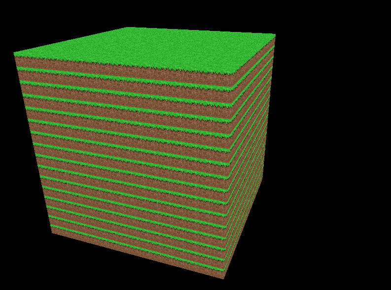
What’s better than one block? Multiple blocks!
To be able to render an infinite world, most games like Minecraft (including Minecraft itself!) use what’s called a chunk system. Minecraft splits the world into slices of 16x256x16 blocks, known as chunks, which are loaded dynamically around the player. These chunks are what stores the actual block data.
For my game I’m doing things a bit smarter than Minecraft here because I’m using something called “cubic chunks.” Instead of having 16x256x16 chunks and loading chunks infinitely in the x and z directions, I’m having 16x16x16 chunks and loading chunks infinitely in all 3 directions. This means I’m able to have an effectively infinite height limit in both directions, so I can get some very deep caves.
(For the curious: there’s actually a mod for Minecraft called Cubic Chunks which adds cubic chunks to the game in the same way I’m planning to do here. Problem is, Minecraft was programmed with a fixed height limit in mind, so that mod causes all sorts of issues, especially when combined with other mods. Having cubic chunks in my game from the start will avoid these problems.)
Right now I don’t have multiple chunks, just one. This week I just wanted to get the chunk actually rendering.
The chunk stores a bunch of block IDs. Right now the only valid IDs are 0, representing air, and 1, representing grass. For the most part, to generate a mesh for the full chunk, I just combine the meshes of all the blocks in the chunk. However, to increase performance, I use a technique known as face culling. When two solid blocks are next to each other, I don’t draw the faces between them. So the interior of the chunk appears hollow when you go inside it. There’s no noticeable difference if you don’t clip into anything though, so for normal gameplay it just makes things run better.
Conclusion
So that’s what I did this last week! I probably won’t go as technically in-depth every week, but going forward I’m gonna try and at least explain the basics of how all the stuff I add works. Hope you all found this interesting!
Things I’m planning on doing by next week include performance fixes, multiple block types, a very naïve form of “lighting,” and a much vaster world to explore.